Digital Filters Arduino
Filtering using Graphical User Interface (GUI)
Using the digital filters through the GUI is very simple, and with just two lines of code, you can open the GUI:
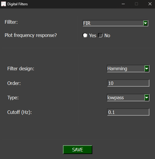
After running the command, the GUI will appear. Navigate to the 'Get Data' screen, where you'll see a radio button to choose whether or not to apply the digital filters. When the 'Yes' option is selected, a new window will appear.
Parameters
-
Filter: Select the type of filter to use — FIR or IIR.
-
Plot frequency response: Choose whether to display the filter's frequency response after data acquisition.
-
Filter design: Select the design method for the filter.
-
Order: Specify the filter order by entering a numerical value.
-
Type: Define the filter type — choose from Lowpass, Highpass, Bandpass, or Bandstop.
-
Cutoff: Set the filter’s cutoff frequency (or frequencies, depending on the filter type).
Real-Time Filter
After configuring the digital filter parameters, they will be applied to the real-time data acquisition, as shown in the image below: